-
Please checkout our new DIY Forum, and any trade that'd like to join and help out, and Contractor Talk Forum.
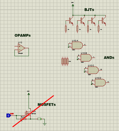


1672785770820.png | ElectriciansForums.net | Free Electrical Advice - Electricians Forums: Electricians' Talk Forums
Originally posted in: Thread 'Logic Outputs Problem in 7493 IC'
OFFICIAL SPONSORS


These Official Forum Sponsors May Provide Discounts to Regular Forum Members - If you would like to sponsor us then CLICK HERE and post a thread with who you are, and we'll send you some stats etc
YOUR Unread Posts
-
 2 x t&e for 3 phase isolatorIt’s a C3. Somewhere in the regs (I would have to have a copy with me to remind myself where!)...
- Latest: Rockingit
-
 Song words.West BOUND And Down View: https://youtu.be/ZmXD_DKNuEs?si=u6f61VjJ2VN09CAx
- Latest: littlespark
-
What pets do you have, and what pets have you had?Just to add to my bunny post above…. A picture my daughter painted a few years ago. We had...
- Latest: littlespark
Media information
Share this media
This website was designed, optimised and is hosted by untold.media Operating under the name Untold Media since 2001.