HappyHippyDad

-
Esteemed
Arms
Supporter
A bit of an embarrassing question.

I have a regular customer who I enjoy working for. He has asked me to install an EV rapid charger for his avant loader (electric tractor type thing). I always turn down 3 phase jobs as I don't feel I understand it fully, but I'd like to do this job.

I believe this is the charger (400V/32A version) Rapid battery charger, e6 - https://www.avanttecno.com/uk/options/rapid-battery-charger-e6

I have added a picture of the 3 phase supply.

1. Are there any additional tests to do, compared with single phase? Phase rotation etc.

2. Is it simply a matter of connecting L1, L2, L3 from the Henly blocks (or perhaps the 3 phase merlin gerlin board) into whatever the instructions say is needed? (eg 30mA RCD)

3. I get a little confused by the role of the neutral in polyphase. Does the neutral have a role in 3 phase or is it simply there to support single phase appliances?
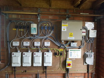
3 phase supply.jpg
3 phase supply.jpg
 
Last edited by a moderator:
1. Are there any additional tests to do, compared with single phase? Phase rotation etc.
EDIT: First point is your safe isolation test has a lot more checks (10 instead of 3)!

L1 to L2,L3,N,E
L2 to L3,N,E
L3 to N,E
N to E

You should verify phase rotation and that phases are correctly assigned all the way (i.e. L1 at the end is from L1 at the supply). Even though most electronic loads don't really care about rotation direction, it is still wrong to not get it right!

The PSCC is usually taken as twice the highest of the three L-N PSCC (on the assumption N has the same impedance as L when measured, and then under the worst-case L1-L2-L3 "bolted 3-phase fault" the virtual neutral has zero impedance).

2. Is it simply a matter of connecting L1, L2, L3 from the Henly blocks (or perhaps the 3 phase merlin gerlin board) into whatever the instructions say is needed? (eg 30mA RCD)
You will almost certainly need the N as well, and some form of OCPD (i.e. fused-switch or MCB/RCD or RCBO)

Taking it from the existing board is fine if there is space and you can get compatible RCBO for it. Ask @westward10 as he seems to know every board ever made!
3. I get a little confused by the role of the neutral in polyphase. Does the neutral have a role in 3 phase or is it simply there to support single phase appliances?
For simple loads like a 3-phase motor you may not need N as it runs off the L1-L3 lines alone.

But in most cases it is needed as there will be some loads to N for single-phase work (e.g. electronic controller for main 3-phase motor, etc), and some "3-phase" units are star-connected and not always balanced (e.g. heater with 3 setting that simply select L1, L1/L2, or L1/L2/L3) so without N the voltages are wrong and potentially dangerously so.
 
Last edited:
As per PC's post, you would definitely need the neutral on the charger as some vehicles can only actually charge on single phase, but they still use the same connector.

All chargers in vehicles tend to need the neutral as they have to be able to use a single phase supply as that might be all that's available.

Specialist vehicles such as fork lifts etc may be different.

Phase rotation won't matter, but should be done right anyhow.
 
EDIT: First point is your safe isolation test has a lot more checks (10 instead of 3)!

L1 to L2,L3,N,E
L2 to L3,N,E
L3 to N,E
N to E

You should verify phase rotation and that phases are correctly assigned all the way (i.e. L1 at the end is from L1 at the supply). Even though most electronic loads don't really care about rotation direction, it is still wrong to not get it right!

The PSCC is usually taken as twice the highest of the three L-N PSCC (on the assumption N has the same impedance as L when measured, and then under the worst-case L1-L2-L3 "bolted 3-phase fault" the virtual neutral has zero impedance).


You will almost certainly need the N as well, and some form of OCPD (i.e. fused-switch or MCB/RCD or RCBO)

Taking it from the existing board is fine if there is space and you can get compatible RCBO for it. Ask @westward10 as he seems to know every board ever made!

For simple loads like a 3-phase motor you may not need N as it runs off the L1-L3 lines alone.

But in most cases it is needed as there will be some loads to N for single-phase work (e.g. electronic controller for main 3-phase motor, etc), and some "3-phase" units are star-connected and not always balanced (e.g. heater with 3 setting that simply select L1, L1/L2, or L1/L2/L3) so without N the voltages are wrong and potentially dangerously so.

As per PC's post, you would definitely need the neutral on the charger as some vehicles can only actually charge on single phase, but they still use the same connector.

All chargers in vehicles tend to need the neutral as they have to be able to use a single phase supply as that might be all that's available.

Specialist vehicles such as fork lifts etc may be different.

Phase rotation won't matter, but should be done right anyhow.

If there are three spare ways in the Merlin board then yes take the circuit from there but you will have to fit a separate rcd as you won't get a four pole rcbo for that board.
Very glad the 3 of you posted, thanks!

A further basic question... so I would take the L1, L2, L3 from a 3 pole MCB that is in the CU (and the N from the neutral bar) to the required 4 pole RCD (or whatever the MI say to take it to). (pic of CU attached).

I'm cringing a bit asking that as I know its such a simple thing. Is it simply the same as taking a supply from a single phase CU to feed whatever it is you want to feed (I.e sub DB, item itself etc) but you have 3 lines instead?

3phase CU.jpg
 
A further basic question... so I would take the L1, L2, L3 from a 3 pole MCB that is in the CU (and the N from the neutral bar) to the required 4 pole RCD (or whatever the MI say to take it to).
Yes, just like that!
<insert Tommy Cooper gag>
I'm cringing a bit asking that as I know its such a simple thing. Is it simply the same as taking a supply from a single phase CU to feed whatever it is you want to feed (I.e sub DB, item itself etc) but you have 3 lines instead?
Mostly this is the case.

It is always better to ask if you don't know!
 
One thing that appears in the picture above is the selection of meters. Will the EV charger need to have its electric usage accounted for separately? If so you might need to put in a billing meter for it that can be used to reconcile usage with the main meter, etc.
 
One thing that appears in the picture above is the selection of meters. Will the EV charger need to have its electric usage accounted for separately? If so you might need to put in a billing meter for it that can be used to reconcile usage with the main meter, etc.
I don't think it will need it's own meter as this will be the owners tractor, I will ask him though as he has asked for meters before on other work around the place.

A 3 phase meter! More questions! 🥺

I've just thought of a bit more in relation to cable size....

Lets say this is the 400V/32A charger.

1. Does each line conductor have to be able to cope with 32A?

2. I realise we have been given 32A in this case, but if we just had the wattage of the charger (lets say 22kW), is the calculation the same as single phase. I.e 22000/400 = 55A?
 
Last edited:
Be extra careful about old and new colours! Old black and blue have exactly opposite functions to new black and blue. If a new circuit you shouldn’t hit this issue though.
IR tests - basically test every permutation.

You’ll be fine, enjoy it, and want to do more!
 
I don't think it will need it's own meter as this will be the owners tractor, I will ask him though as he has asked for meters before on other work around the place.

A 3 phase meter! More questions! 🥺
If needed then something like this should do and does not need a separate enclosure:

I've just thought of a bit more in relation to cable size....

Lets say this is the 400V/32A charger.

1. Does each line conductor have to be able to cope with 32A?
Yes, if that is the spec.

Check the cable tables though as the rating for, say, 6mm, is different if single phase or three-phase as more I^2*R losses per bundle.

2. I realise we have been given 32A in this case, but if we just had the wattage of the charger (lets say 22kW), is the calculation the same as single phase. I.e 22000/400 = 55A?
No your equivalent is 22000 / (3 * 230) = 32A

If you imagine a star-connected load, then you can see that each L current with the L-N voltage gives you 1/3 of the total power.

The equivalent delta case (400V L-L) is more complicated as each L current is shared by two of the arms (say L1 has loads going to both L2 and L3), and not in-phase to make any calculation simple. Answer is 22000 / (sqrt(3) * 400) and is the "same" (though 400V L-L is not exactly the same as 230V L-N)

TL;DR: So just work with the star model as it gives the same answer!
 
Last edited:
Something worth considering with three-phase charge points is that the phase sequence should actually be varied between units. So if there is a charge point connected L1-L2-L3 then an additional unit should be L2-L3-L1 or L3-L1-L2. This is to prevent them all pulling off the same phase where the vehicle is only capable of single phase charging. Obviously maintain the phase rotation though.
 
the actual circuit is standard 3 phase from what i can see, not sure if it needs PEN fault or Type A rcd etc as its not a standard ev charger within the code of practice etc.
I'll try and find some specs for the unit, but something like this may be suitable?
Is this the standard price for a 3 phase Matt e, expensive!
 
I'll try and find some specs for the unit, but something like this may be suitable?
Is this the standard price for a 3 phase Matt e, expensive!
Yeah - CEF are actually one of the cheaper wholesalers for Matt:e O-PEN devices.
 
Some more...

In the picture in the OP, you can see a separate small enclosure housing a 4 pole RCD (300mA). This feeds the 3 phase CU (and the agricultural single phase meters) where I will be taking power from. I'm guessing this will be a type AC RCD which is going to be a problem if I then need a Type A (or B) RCD downstream to this for the charger.

Am I going to have to change this RCD to the relevant type? They look like a ridiculous price!
Or, I could take the supply from the henley blocks to the left of the 300mA RCD which have no RCD protection? This seems better, as the cable from the Henly blocks to sub DB will not need RCD protection and I could locate it close to the henley blocks in the same room.
 
Last edited:
I'll try and find some specs for the unit, but something like this may be suitable?
Is this the standard price for a 3 phase Matt e, expensive!
Given the cost of the matt:e and it being a farm could you not get a rod in using some machinery?
Like wise if its being used solely inside then use the pme.
 
Given the cost of the matt:e and it being a farm could you not get a rod in using some machinery?
Like wise if its being used solely inside then use the pme.
A rod may be the way forward as the tractor could be charged outside.
 
Some more...

In the picture in the OP, you can see a separate small enclosure housing a 4 pole RCD (300mA). This feeds the 3 phase CU (and the agricultural single phase meters) where I will be taking power from. I'm guessing this will be a type AC RCD which is going to be a problem if I then need a Type A (or B) RCD downstream to this for the charger.

Am I going to have to change this RCD to the relevant type? They look like a ridiculous price!
Or, I could take the supply from the henley blocks to the left of the 300mA RCD which have no RCD protection? This seems better, as the cable from the Henly blocks to sub DB will not need RCD protection and I could locate it close to the henley blocks in the same room.
Yes the upstream device will need to be at a minimum Type A (assuming DC Leakage protection in the EVSE), otherwise Type B. Obviously also S-type (time delayed).

For example a number of EVSEs I installed for a well-known courier firm I replaced the upstream S-type RCCB for a Type A 300mA for the distribution circuit. This went to a switch fuse and then onto the DBs. I had triple pole circuit breakers in the DBs feeding four pole RCCBs. (It was a TT installation.)
Is there a reason why I shouldn't just bypass the 300mA RCD by using the Henley blocks upstream?
Meter tails into a separate enclosure housing all the bits I need.
 
Something worth considering with three-phase charge points is that the phase sequence should actually be varied between units. So if there is a charge point connected L1-L2-L3 then an additional unit should be L2-L3-L1 or L3-L1-L2. This is to prevent them all pulling off the same phase where the vehicle is only capable of single phase charging. Obviously maintain the phase rotation though.
I had always assumed that EV chargers are like old 12V charger or many 3-phase UPS where they would use all phases to generate the DC for charging, but I guess they supply AC to the EV for that?

A very good point to spread the load over the phases!
 
Is there a reason why I shouldn't just bypass the 300mA RCD by using the Henley blocks upstream?
Meter tails into a separate enclosure housing all the bits I need.
That would appear a better option if you can get a suitable RCBO or similar.

It might be the Matt:e with RCBO is suitable, but check what it needs up-stream. At the very least it would need an isolator, but you might be better with a 3PN switched-fuse with something like 40A-50A fuses to give total selectivity with 80-100A incomer fuses.

I see there is an isolator at the incomer which is great, but I would rather not have to totally shut down such a large installation just for any future EV problems being fixed.
Could you tell me why the Matt:e would need a separate isolator? It has a 5 pole mains isolator which could be used to isolate from the other electrics if a fault occurred.
 
Given the cost of the matt:e and it being a farm could you not get a rod in using some machinery?
Like wise if its being used solely inside then use the pme.
Actually I don't think a rod will be possible. The charger will be housed in the meter room. The meter room has PME earthing terminals in it which will be simultaneously accessible with the charger (or tractor when it is being charged). Looks like it has to be Matt:e! Hopefully the charger has a PEN fault device already!
 
...
Or, I could take the supply from the henley blocks to the left of the 300mA RCD which have no RCD protection? This seems better, as the cable from the Henly blocks to sub DB will not need RCD protection and I could locate it close to the henley blocks in the same room.
Yes, take tails from the Henry blocks into a kmf, swa to the charge point (assuming the charge point has integral rcd protection etc)
If the charge point doesn't have integrated protection, then instead of a kmf, use an rcbo, rcd/mcb, or rcd/fuse combination.

(Assuming supply is tncs or tns)

if TT then in both cases you would need a delayed rcd after the tails.
All sounds good, thanks Julie.
I shall hopefully read the spec of the charger on Monday.
As above, I don't think TT is an option as it will be simultaneously accessible to PME.
 
Is there a reason why I shouldn't just bypass the 300mA RCD by using the Henley blocks upstream?
Meter tails into a separate enclosure housing all the bits I need.
You can call me old fashioned but I prefer to maintain an S-type upstream for at least some redundancy and fault protection for the cables feeding the DB.
 
I had always assumed that EV chargers are like old 12V charger or many 3-phase UPS where they would use all phases to generate the DC for charging, but I guess they supply AC to the EV for that?
Yes, they supply AC straight to the EV for it to do the DC conversion. It's also worth mentioning that 95% of electric vehicles cannot handle more than 11kW AC or 16A per phase. There are very few EVs that can actually make use of the full 22kW.
 
You can call me old fashioned but I prefer to maintain an S-type upstream for at least some redundancy and fault protection for the cables feeding the DB.
But wouldn't they already have fault protection given that its ADS with a good Ze (0.15ohms)?
I would completely agree if it was TT, it would then be a necessity.
Are you just saying it's a good idea to have as well as ADS?
 
But wouldn't they already have fault protection given that its ADS with a good Ze (0.15ohms)?
I would completely agree if it was TT, it would then be a necessity.
Are you just saying it's a good idea to have as well as ADS?
Yes sorry I was referring to where a TT system exists. It wasn't intended to suggest that I consider it necessary for TN systems.
Apologies for the confusion.
 
I had always assumed that EV chargers are like old 12V charger or many 3-phase UPS where they would use all phases to generate the DC for charging, but I guess they supply AC to the EV for that?

A very good point to spread the load over the phases!
EV chargers do use all three phases, convert to dc and pass this to the vehicle.

However, I think the op is installing an EV Charge Point (EVCP) which merely connects either single phase 230V or three phase 400V to the vehicle, in which case the charger is within the vehicle.

When connected to an EVCP the charge rate is limited by the lower of the EVCP (32A, 16A, 10A ) or the rating of the charger within the vehicle (might be 9.2kW)

Whereas with an EV charger, you can have very high charge capacity 50kW, 70kW, 150kW etc.

These rapid chargers are pretty big bits of kit though.
 
Yes sorry I was referring to where a TT system exists. It wasn't intended to suggest that I consider it necessary for TN systems.
Apologies for the confusion.
I think the up-front 300mA RCD here is due to it coming under agricultural areas and for fire risk reduction. Supply seems to be TN-C-S.

But I agree with you that for TT systems I would always prefer a delay RCD as incomer and then RCBOs afterwards, as no *single point of failure that could leave the CPC live.

[*] Single here as in fault in a RCD not spotted by **anyone doing a periodic test, clearly it needs two fault: some L-CPC fault and then the RCBO/30mA RCD not working.

[**] AKA friends of the seal faery.
 
Could you tell me why the Matt:e would need a separate isolator? It has a 5 pole mains isolator which could be used to isolate from the other electrics if a fault occurred.
If it is easy to isolate internally then you would not. It kind of depends on the trouble caused to isolate the whole system to work on the Henley blocks and feed to Matt:e versus the cost/space needed for some form of isolation.

It also depends on what the Matt:e requires in the way of any input protection / max supply PSCC. If it is fine with 100A fuses, etc, for example if has a MCB/RCBO as the only incoming connection and that can break 6kA, then not needed.
So it's looking like this charger just requires a 5 pin 16A commando socket and that this scenario isn't part of section 722 as its just ELV on the vehicle.

I was hoping to run past you (and others, just happened to quote you) my final (hopefully) thoughts as this is my first delve into 3 phase.

Change the 3 pole mcb in the 3 phase board for a C20. Take from this to a separate small CU housing a 4 pole Type AC RCD. From there I go to the commando socket (or possibly bypass the CU and just have the required RCD combined in the commando socket)? Probably all in 5 core 2.5mm H07RN?

I have chosen a Type AC RCD for poor reasons. There is an upstream 300ma RCD which I was trying to avoid changing to a Type A. Also, type AC RCD's are 'usually' acceptable (i.e meet the regulations) to use to protect sockets.

I am unsure how to ascertain if a type A is required as I cant get anybody at Avant who understands what DC leakage is and how likely it is with the charger/loader.

Main question is the highlighted bit though.
If 722 doesn't apply, then my understanding is that a 30mA type AC meets the requirements for a socket < 32A and reg 411.3.3 as you said.

I fitted a 4 pole type A RCD recently (MCG branded from CEF) and there was no difference at all in cost between the type A and type AC. Both were about £50, so might as well fit a type A and you've gone above and beyond.
 

OFFICIAL SPONSORS

Electrical Goods - Electrical Tools - Brand Names Electrician Courses Green Electrical Goods PCB Way Green 2 Go Pushfit Wire Connectors Electric Underfloor Heating Electrician Courses Heating 2 Go Electrician Workwear Supplier
These Official Forum Sponsors May Provide Discounts to Regular Forum Members - If you would like to sponsor us then CLICK HERE and post a thread with who you are, and we'll send you some stats etc

Advert

Daily, weekly or monthly email

Thread starter

HappyHippyDad

Esteemed
Arms
Supporter
-
Joined
Location
Gloucestershire
If you're a qualified, trainee, or retired electrician - Which country is it that your work will be / is / was aimed at?
United Kingdom
What type of forum member are you?
Practising Electrician (Qualified - Domestic or Commercial etc)

Thread Information

Title
Installing a 3 phase rapid EV charger?
Prefix
N/A
Forum
UK Electrical Forum
Start date
Last reply date
Replies
64
Unsolved
--

Advert

Thread statistics

Created
HappyHippyDad,
Last reply from
Risteard,
Replies
64
Views
13,657

Advert

Back
Top